
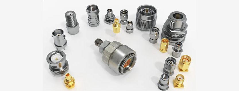
There are many RF connections in modern RF systems and devices. Often, when designing an RF device or system, considerable attention is paid to selecting and evaluating various RF instruments. Sometimes overlooked but equally important are the RF interconnections: the connectors, cables, adapters, circuit boards, and other components that carry the signal from RF instrument to RF instrument. In this article, Mini-Circuits will refer to the entire category of RF interconnections as RF connectors. Proper connector care is essential for overall performance in RF systems and devices. Let’s look at the layers of RF connector care that should be included in the overall best practices.
To begin, our budget should be sufficient to purchase high-quality connectors. High-quality parts provide better accuracy, repeatability, and a longer life. Next, a thorough, regular visual inspection and cleaning, as needed, should be performed. Cleaning with 100% isopropyl alcohol is recommended. Any damaged or worn connectors should be thrown away.
Periodically, connectors should be gauged with a high-quality, calibrated connector gauge kit. Gauges measure the depth of the center pin relative to the connector’s mating plane, ensuring a proper fit and preventing mechanical damage.
Finally, we want a stable, repeatable connection between two connectors. Some connectors, such as APC-7, BNC, TNC, and some N-type connectors, can only be tightened by hand. However, others, such as the SMA, 3.5mm, 2,92mm, 2,4mm, 1.85mm, and 1,0mm, are designed to be secured with a torque wrench, providing a stable, repeatable connection while avoiding damage to the connector.
Let’s take a closer look at properly mating an RF connection to minimize wear and prevent damage while improving repeatability and accuracy. The following example uses an SMA RF connector, which is typical on many RF cables. A similar approach is used on all RF precision connectors.
To begin, confirm you have a calibrated torque wrench set to the proper torque. If a calibrated torque wrench is not available, finger-tighten the connection by securing the coupling nut until one is located. Never tighten an RF connection with standard generic wrenches, as there is a significant risk of over-tightening, which can cause permanent damage to the connectors.
To properly tighten an RF connection:

Figure 1 – The coupling nut and anti-torque nut of a high-quality 3.5 mm RF connector.

Figure 2 – Properly tighten the RF connection.
Be aware that the tendency (especially when using your fingers to tighten the connection) will be to hold the coupling nut and spin the anti-torque nut connected to the cable. This causes the center pin to spin inside the center collet as the connectors are mated. The resulting mechanical friction shaves the plating off of the center pin, resulting in premature wear, reduced performance, and debris trapped in the connector. This is evident on the N-Type connector shown in Figure 3.

Figure 3 – Debris from repeated improper connector mating.
Also, note that while the overwhelming number of connectors are 50-ohm impedance, 75-ohm impedance connectors are also common. These two connector families may look strikingly similar. However, they are not interchangeable and mating them together will result in significant connector damage. This is illustrated in Figure 4. Note the difference in the center pin diameter of a 50 versus 75 ohm N-type connector.

75 Ohm 50 Ohm
Figure 4 – N-Type 50 and 75 ohm connectors. Note the difference in center pin diameter.
Overall, the treatment of RF connections and the process of making a proper secure connection are just as important as the performance of the instruments and components used in the system. Incorporating connector care and best RF practices into your measurement routine will ensure quality, consistent RF results.
Get in touch for orders or any queries: sales@rfdesign.co.za / +27 21 555 8400
Courtesy of Mini-Circuits