RF Measurement Devices in Modern Production Test Lines
Modern Manufacturing
Manufacturing modern electronic devices and products places a high demand on cost, schedule and quality and simply trying to optimize 2 of these 3 performance attributes can be challenging. Driven by customer requirements as well as advances in technology, “what is possible” is rapidly changing across the manufacturing realm. This is especially true of RF devices which operate at progressively higher frequencies and power levels. Device innovation is a catalyst for the expansion of the addressable market, meeting the challenges of increasing frequency and power requirements.
For example, automotive radar, in wide use today with features such as lane departure and adaptive cruise control, were virtually unknown just a decade ago. High performance RF products and devices for these applications were relegated to high cost, high performance areas such as aerospace and defense. As innovation continues, RF becomes a rapidly growing part of the electronic landscape. A thorough understanding of and appreciation for the manufacturing process itself affords opportunities to reduce costs and improve throughput.
The Traditional or Typical Manufacturing Line
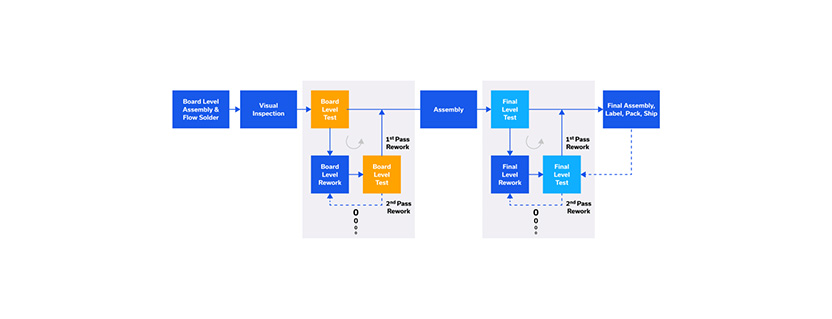
Let’s begin by examining the workflow for a typical manufacturing line as shown in Figure 1, targeted at high volume, low mix products. Mobile phones for example.

Figure 1: A typical high-volume, low-mix assembly line with board and final feedback rework cycles
Solder paste is first deposited on the printed circuit board (PCB, or “fab”). A mask is often laid over the PCB so that the solder paste is placed where the component leads are to be secured. With high-volume products, this is done with a “pick-and-place” machine where a pre-programmed automated “robot” places components on the PCB. The PCB with the components properly placed is then passed through a multi-zone flow solder machine (“oven”), heating the solder paste and allowing the solder to reflow and permanently affix the components to the PCB. A visual inspection generally follows to verify the board has been assembled correctly. For high volume manufacturing, this operation is often performed as automated optical inspection (AOI), where the solder reflow process integrity is verified for each component from a multitude of camera angles.
The assembled PCB then enters its first test station, which we will refer to as the board-level test station. Prior to testing, there is often firmware/software to be downloaded to the assembly. Board level test then begins with basic functional testing such as applying power and verifying the contents of memory. This is followed by higher level tests. For example, if the device is a mobile phone, parameters such as frequency, power and modulation would be tested at this point. These parameters can be passed to a test station down the line to verify the device is operating properly after final assembly.
Board-Level Test
At board-level test, it is necessary to keep track of both the number of units that pass the first time through test and to identify and count all failures or out-of-limit measurement parameters. The number boards passing the first time out of the total number tested is referred to as the first-pass yield. If the components, labor and use of capital equipment is economical enough, some products that fail testing
or are not within the test limits can simply be discarded, or “scrapped.” However, this is most often not the case. Therefore, to address failures or parametric yield problems at board-level test, a rework strategy must be implemented.
If a unit fails board level test, it is removed from the line and sent to a rework station. Here, it is tested to verify the failure and to be reworked. Note that rework resources, labor, equipment, etc., are not infinite. Consequently, a scrap policy should be developed as part of the overall rework strategy. For example, through financial analysis it has been determined that a board will scrapped if the assembly cannot be brought into compliance after 30 minutes of time and $30 in materials are expended in an effort to rework it.
If the board is successfully reworked, it is placed back on the line with other untested units from the PCB assembly station to be retested in the board-level test area. If the reworked board fails again, it can go back to the rework station or be scrapped depending on the economics of the repair loop defined by the rework strategy.
Notice as well that every reworked board that is placed back on the line to be retested displaces a newly assembled, pristine board that is going to test for the first time. This configuration is referred to as a feedback rework strategy and is highlighted in Figure 1.
Feedforward vs. Feedback Rework Approach
As warranted by for instance first-pass yield and/or capex budgetary constraints, a separate board level test station may be constructed exclusively to rework and retest failed PCB assemblies. The reworked board can then be placed back on the manufacturing line at a point downstream from the board level test station in what is referred to as a feedforward rework strategy. The workflow and configuration of this strategy is shown in Figure 2.

Figure 2: A typical high-volume, low-mix assembly line with board and final feedforward rework cycles
While a feedforward approach requires the cost of an additional test station(s), it does not interrupt the flow of new, untested units arriving at test directly from assembly. Focusing for the moment on the feedback strategy, and assuming that the reworked board assembly passes test and moves down the line, that board assembly will continue down the line to be combined with various other components and sub-assemblies. The product is completely assembled to at least 90% of its final configuration.
Final Test
Just as boards are subjected to board-level testing, the “product” or “unit” is passed into the final test stage. Final test begins with basic functional tests such as power and button push, then advances to more sophisticated tests such as RF power, frequency and modulation quality. As with the board test station, if any unit fails final test, whether catastrophically or parametrically, it is sent to a rework station.
The rework cycle may be laid out in a feedback or feedforward configuration, exactly as shown for board-level test. After rework, the product is retested. Assuming the unit passes, it moves on to final assembly, where its 90% final configuration is turned into 100%. At this point, items such as labels, serial numbers and other final items are placed on the product which is then packaged and readied for shipping. If any defect, or, worst-case damage is discovered at this point, the unit is sent back through the rework cycle, including final test. Operations at this point are relatively benign, so the number units affected should be inordinately small.
Yield
We need to be mindful of a metric referred to as first-pass yield at both board test and final test. That is to say, how many units are passing the first time they are tested? Yield is the number of pristine (“fresh”, or “untested”) units that pass testing on the initial run through the test station, divided by the total number of units (pristine + failed units) tested over a given timeframe. Yield, or more specifically first-pass yield, is represented as a percentage. The composite yield of the entire line is defined as the board test yield x the final test yield. For modern day top tier manufacturing yields are well above 90%.
Additional Metrics
In addition to yield, underlying a modern manufacturing line are further processes, data and metrics. It is important to measure the performance of the manufacturing line in real time. For instance, where is the bottleneck? That is, where is the flow constricted. The bottleneck only occurs at one place, but it can change location with time. Failure analysis is another important tool. What test(s) and measurement parameter(s) are most commonly failing? How often? What are the root causes? What are the corrective actions? What is the throughput? Is it trending up or down? Does the same measurement track across all test stations? Understanding these underlying processes and their test results are essential to ensuring optimal throughput while also controlling costs.
Especially with RF, are we using high quality components and instruments that are replaced or calibrated regularly? Further, what is the condition of the test equipment? Are high performance cables, adapters, filters, amplifiers, power sensors, etc being used and inspected regularly?
Final Stage
Modern manufacturing is complicated, driven by advances in RF components and assemblies, and increasingly complex RF products and applications. In a few short paragraphs, modern manufacturing strategy has been discussed, and both the feedback rework cycle and feedforward rework cycle have been described. Final assembly, first-pass yield and other performance metrics were mentioned along with a series of questions to use for guidelines as a check on the integrity of the manufacturing process. Understanding the construction of a modern manufacturing line, its components, processes, metrics, and instrumentation is essential to the success and profitability of any operation.
Courtesy of Mini-Circuits