Using S-Parameter Files to Model Small- and Large-Signal Amplifier Performance in ADS®
This application note was prepared in response to recent customer requests for guidance on using ADS to model the small- and large-signal performance of Mini-Circuits amplifiers based on published S-Parameter data in .s2p format. The following sections describe how to use .sNp and .txt files to model small- and large-signal performance. We also demonstrate large-signal modelling using both the Amplifier2 and AmplifierS2D behavioral models in ADS, including compression parameters and third-order intermodulation distortion (IP3).
Small Signal S-Parameter Model
Complex S-Parameter data is provided on the Mini-Circuits website for essentially all components using .sNp or .txt file formats. These resources allow ADS® to model and plot cascaded small-signal performance using the .sNp and .txt file formats. See Figure 1 below for an example.

Figure 1: sNp data item in ADS.
Larger Signal Behavioral Models
ADS can simulate cascaded small- and large-signal behavior (Pout, Gain, IP3, Harmonics vs. Pin) using published S-Parameter data, ADS amplifier behavioral models, and Harmonic Balance simulation.
One technique uses the ADS Amplifier2 behavioral model and a Generalized Multi-dimensional Data (.mdf) file. The .mdf file is derived from published S-Parameter data by modifying the header line and adding Begin and End statements. The original .s2p and newly generated .mdf file formats for the PHA-102+ amplifier are shown below.
Original:

Modified:


The variable names freqW, S11dB, S11Ang, S21dB, S21Ang, S12dB, S12Ang, S22dB, and S22Ang used in the format line (%) are user-defined and arbitrary but must be referenced in the ADS schematic file. The term (real) indicates a real-number entry. Each variable in the format line (%) defines the order of data in the lines that follow.
The DAC element (Data Access Component) acquires the data associated with each variable. Detailed information regarding .mdf files may be found in the Agilent Technologies Advanced Design System tutorial, “Using Circuit Simulators.”
Variable Definitions
As shown in Figure 2, required parameters are pulled from the DAC using Data Item blocks VAR1–VAR5.

Figure 2: Variable, S-Parameter and Parameter Sweep blocks in ADS Amplifier2 model.
Parameter Sweep Definitions
The Parameter Sweep block defines the sweep variable (SweepVar), arbitrarily defined as freqW. It must also specify the S-Parameter or Harmonic Balance instance name referenced in simulation blocks. Start and stop frequencies are defined using the sweep variable. Step size or points per decade may also be specified.

Figure 3: Parameter Sweep block settings in ADS.
S-Parameter and Harmonic Balance Frequency Definitions
For S-parameters, start and stop frequencies are specified using the variable freqW. The step size should match the Parameter Sweep definition. For harmonic balance, the fundamental frequency is defined by freqW, and the number of harmonics must also be specified.
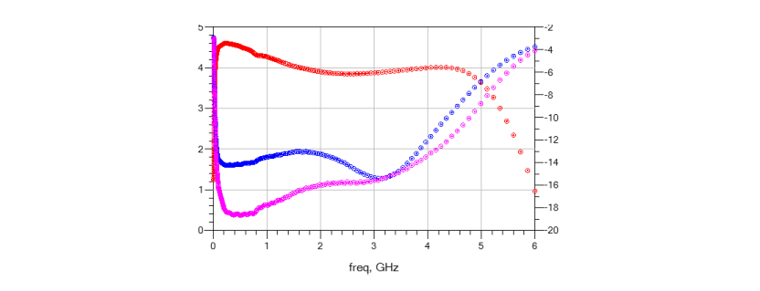
Small Signal Results (S-Parameters)
The 2-port S-parameters for the PHA-102+ are obtained by running an S-parameter simulation, as shown below.

Figure 4: S-Parameter simulation of PHA-102+ MMIC amplifier.
These results are identical to those obtained using the original .s2p file provided by Mini-Circuits.
Large Signal Results (Harmonic Balance): Amplifier2 Behavioral Model
Large-signal performance can be modeled using the Amplifier2 behavioral model and Harmonic Balance simulation.

Figure 5: Amplifier2 behavioral model used for large-signal simulation.
Simulated large-signal parameters (Pout vs. Pin and Gain vs. Pin) are shown below for a 6 GHz carrier frequency.

Figure 6a: Power sweep parameters in Harmonic Balance block.


Bottom Line
A significant amount of information can be obtained using published S-parameter data. Many design engineers already use these techniques in their workflows. For those unfamiliar with the full utility of these resources, this note provides practical modelling methods for both small- and large-signal performance in ADS.
You can try these modelling techniques using the provided S-Parameters for all Mini-Circuits amplifiers.
Get in touch for orders or queries: sales@rfdesign.co.za / +27 21 555 8400
Courtesy of Mini-Circuits