Comparative Analysis of High-Rejection LTCC Filters with Monoblock Technology
Need for Smaller and Higher Performance Drives Technology Upgrade
Beginning in 1965 and for approximately 50 years, transistor density in integrated circuits followed Moore’s Law. Yet during the last 15 years, active RF electronics have evolved into the RF System-on-a-Chip (RF SoC) and RF System-in-a-Package (RF SiP) approaches, which have led to significant SWaP-C (Size, Weight, Power and Cost) reduction and simultaneously enhanced processing power. SWaP-C reduction is in as high a demand as ever in passive RF electronics as well, where RF Engineers continue to be squeezed for both higher performance and higher volumetric efficiency. Mature technologies have built a strong legacy of passive RF components, but to meet modern SWaP-C demands, many are being replaced with newer technology components in a process known as a technology upgrade.
One passive RF component that is ubiquitous throughout RF systems is the traditional band pass filter. Some of the more mature band pass filter technologies are found in Lumped Element, Alumina, Ceramic Resonator, and Ceramic Monoblock filter construction techniques. Tuning, etching, soldering, drilling, and plating are just some of the operations required. These mature filters are widely used in virtually every defense and commercial market, with a number of applications on the receive side alone being preselection, image rejection, IF and LO filtering, channelization, and antialiasing.
Recently, Mini-Circuits’ introduced the BFHK high-rejection LTCC band pass filter product line, which is more compact and exhibits far greater stopband rejection than many mature technology filters. RF Engineers, for whom achieving high system dynamic range in a small footprint are paramount, have noticed the BFHK-series’ tiny footprint, sharp transitions and deep rejection levels. In this article we describe the performance characteristics of Mini-Circuits’ BFHK-series LTCC band pass filters as well as those of ceramic monoblock filters. We then draw a direct comparison between two filter models from the BFHK-series and their nearest counterparts in ceramic monoblock technology. Applications and use cases for high-rejection LTCC filters are discussed in light of their utility in receiver design. We conclude with a clear rationale for the high-rejection LTCC technology upgrade that is beginning to occur in the commercial and defense markets.
BFHK Filter Performance Characteristics
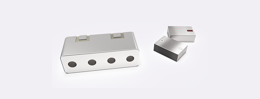
Mini-Circuits’ BFHK-series of ultra-high stopband rejection LTCC filters supports the drive towards RF/microwave circuit miniaturization by combining outstanding selectivity and high stopband rejection with the size, cost and repeatability of LTCC components. The optimum performance shown on data sheets for the BFHK-series of filters is measured when mounting the NM1812C-3 package’s 0.012 in. [0.3 mm] center conductor, shown on the righthand side of Figure 1, directly to a 0.012 [0.3 mm] pad on a stripline circuit board. Mini-Circuits addresses the practical challenges of interfacing with a full range of circuit board design techniques that differ from stripline with the BFHKI-series of filters. This series incorporates a versatile interposer to accommodate other circuit board technologies and trace geometries, including coplanar waveguide and microstrip. The performance between the BFKH and BFHKI-series filters is comparable. For the purposes of this article, we will focus our attention on the BFHK-series.

Figure 1: Mini-Circuits’ BFHK-series high-rejection LTCC vs. Monoblock Brand Y band pass Filter mechanical outlines
The construction and fabrication of LTCC components make for a rugged and reliable platform from which to springboard. Case in point, the BFHK-series of LTCC high-rejection band pass filters operates over a -55⁰C to +125⁰C temperature range, exhibit rock solid frequency response vs. temperature, and include passbands all the way to 19 GHz. With low insertion loss for sensitive systems and stopband rejection that is often 80 to 100 dB or even higher, BFHK-series band pass filters are excellent for systems requiring operation with high dynamic range.
Monoblock Filter Technology Description and Performance Capabilities
Ceramic monoblock filters are a type of ceramic resonator filter in which the series of ceramic resonators has been molded into a single block at high temperature. Monoblock filters are more compact than their discrete resonator counterparts since they are molded as a single unit, include all capacitive coupling, and can be soldered directly to a circuit board. The lefthand side of Figure 1 shows a ceramic monoblock filter.
Ceramic monoblock band pass filters are characterized by excellent insertion loss in the passband, and steep skirts in the transition band. Their stopband rejection averages in the 30 to 50 dB range, and as a standalone band pass filter it is often insufficient for RF systems with a dynamic range that exceeds 60 dB. The size of ceramic monoblock filters is small, but ceramic monoblock technology no longer yields filters with the most compact form factors. For instance, Figure 1 shows that the height and the width of the ceramic monoblock filter is constrained by the dimensions necessary for molding the resonators. The length, of course, determines the band pass filter center frequency. While Figure 1 is a useful comparison, keep in mind that ceramic monoblock filters often require additional hardware for shielding, which consumes even more circuit board space.
A Comparison between BFHK High-Rejection LTCC Filters and Monoblock
Figure 1 has been drawn to scale to show the difference in size between the BFHK-series NM1812C-3 package and the Brand Y monoblock component (note that Brand X is significantly larger than Brand Y). The BFHK LTCC filter footprint is 63% smaller than the footprint of the ceramic monoblock, and this does not include any of the recommended shielding needed to comprise a complete monoblock assembly. Since the BFHK is 50% shorter than the monoblock at only 1.5 mm in height versus the Brand Y monoblock’s 3 mm, the BFHK LTCC filter volume turns out to be 80% smaller than the ceramic monoblock filter. This significant reduction in size affords designers greater flexibility in circuit board layout. The volumetric efficiency of BFHK-series band pass filters is just one characteristic that has accelerated the adoption of these filters by RF Engineers for numerous applications.
Performance is not compromised in the stopband for the smaller BFHK-series filters when compared to the Brand X and Brand Y monoblocks; it is enhanced. In Figure 2, the insertion loss vs. frequency is shown for the BFHK-5001+ 4.9 GHz band pass filter and the Brand X component. The filters were chosen based on the similarity of their RF center frequencies and 3 dB bandwidths.

Figure 2: Insertion Loss vs. Frequency for Mini-Circuits’ BFHK-5001+ and Monoblock Brand X Band Pass Filters
The filters share very similar roll-off characteristics and a nearly identical 30 dB bandwidth. For the monoblock filter, the stopband rejection is only 50 dB at frequencies below the passband, and just 30 dB for frequencies exceeding the passband. The BFHK-5001+ exhibits 80 dB of rejection below the passband and approximately 75 dB above. Tens of dB of improvement in stopband rejection in a significantly smaller footprint enables designers to achieve higher dynamic range in smaller enclosures, which is absolutely critical in many receive-side applications.
Continuing with the comparison, Figure 3 shows the BFHK-6751+ 6.4 GHz band pass filter insertion loss and the Brand Y ceramic monoblock band pass filter insertion loss overlayed on a single chart.

Figure 3: Insertion Loss vs. Frequency for Mini-Circuits’ BFHK-6751+ and Monoblock Brand Y Band Pass Filters
The much larger Brand Y monoblock component has a lower passband insertion loss than the tiny BFHK high-rejection LTCC filter, an advantage that comes at the price of nearly three times the footprint. The Brand Y monoblock band pass filter even exhibits a very steep and relatively deep roll-off for its lower skirt, but its stopband rejection of 65 dB is bested by the BFHK-6751+ by 30 dB or more. At frequencies above the passband, the test data available on the monoblock Brand Y data sheet does not show the filter achieving 30 dB of rejection while the BFHK-6751+ moves past 60 dB at 8 GHz towards 95 to 100 dB beyond 8.5 GHz.
The advent of Mini-Circuits’ high-rejection LTCC filters is important not simply due to burgeoning circuit densities, although this reason is important. Perhaps more importantly, Mini-Circuits’ BFHK high-rejection LTCC filters enable many modern systems to operate with very low-level signals by greatly attenuating adjacent channel interference so that it does not affect system sensitivity. In multi-channel systems, channel-to-channel crosstalk specifications are tightening as system dynamic range increases. Radiative launches and the housing of multiple resonators make it difficult to confine stray fields to the ceramic monoblock band pass filters, meaning that shielding frames are often recommended, or even required. While BFHK-series high-rejection band pass filters do require attention to detail in layout, traditional stripline launches have achieved excellent results. Even the BFHKI-series, with an interposer board to accommodate coplanar waveguide and microstrip, performs exceptionally well in terms of stopband rejection when appropriate measures are taken in electrical and mechanical layout. Often the BFHK-series band pass filters are not the limiting factor, and they are capable of performing beyond the rejection limit of the host enclosure.
One final note about performance over temperature. Both BFHK high-rejection LTCC band pass filters and ceramic monoblock band pass filers perform well over temperature, but the BFHK-series is rated to operate from -55⁰C to +125⁰C, with the data sheet showing frequency response curves that virtually overlay one another. This performance is something the ceramic monoblock technology band pass filters cannot achieve, as their operating temperature range is limited to between -40⁰C and +85⁰C. The high temperature performance of the BFHK filters is important since one byproduct of the ever-shrinking RF system is having the same heat confined to a smaller area, yielding higher temperatures. It’s not surprising to see localized RF system temperatures exceed 90⁰C or 100⁰C. Performance at the low temperature extreme is of particular importance in the aerospace and defense market.
Applications and Use Cases – Preselectors and Image Rejection Filters
Common applications of band pass filters are front-end preselectors and image rejection filters. There has long been the need for RF receivers to incorporate high-selectivity preselectors in the front end. The preselector is the first line of defense against high-level interferers adjacent to the passband that may desensitize the receiver. BFHK high-rejection LTCC filters can perform the function of the preselector for passbands up to 27.5 GHz. The low insertion loss, steep roll-off and high stopband rejection are ideal for attenuating out-of-band noise and interferers. Figure 4 shows a simple example of a compact, point-to-point microwave front end with the BFHK filter utilized as the preselector.
- Preselector: 24000 – 27500 MHz (2.23 dB insertion loss)
- LNA: 20.41 dB gain at 26500 MHz
- Attenuator: 3.15 dB at 26000 MHz

Figure 4. Point-to-point microwave front end block diagram with the BFHK-2582+ as the preselector
In superheterodyne receivers, the image rejection filter is located downstream from the preselector, and generally behind the LNA. The image, located on the opposite side of the LO from the desired passband, must often be attenuated by a minimum of 60 dB (image rejection), and sometimes by as much as 80 dB. BFHK LTCC high-rejection filters make excellent image rejection filters because their steep skirts and high stopband rejection enable them to rapidly transition from passband to stopband and to highly attenuate the spectral band known as the image.
Summary – The Rationale for Band Pass Filter Technology Upgrade
In this article we compared the mechanical and electrical attributes of the Mini-Circuits’ BFHK-series high-rejection LTCC filters with those of traditional ceramic monoblock technology components. While the insertion loss of ceramic monoblock filters is lower, the BFHK-series LTCC filters achieve tens of dB higher stopband rejection in a case that is one fifth the size and operates from -55⁰C to +125⁰C with excellent temperature stability. The preselector and image rejection filter applications emphasize the necessity to greatly attenuate interfering signals in adjacent bands, or even the image itself. System dynamic range requirements often exceed 100 dB, rendering the 30 dB of rejection provided by the ceramic monoblock filter insufficient, even when supplemented by other filter means.
High dynamic range, high circuit density, and high operating temperature systems demand a new filtering technology. Mini-Circuits has met that demand with the BFHK-series of high-rejection LTCC filters. The BFHK-series’ popularity is growing as market forces drive technology upgrade. This drive exists for multiple markets such as SATCOM, Test & Measurement, Quantum Computing, and Aerospace and Defense. As RF Engineers continue to be squeezed for higher RF system performance and tighter circuit board layouts, this technology upgrade trend is expected to continue.
Courtesy of Mini-Circuits