SATCOM Shifts Reference Frequency from 10 to 100 MHz – A System Perspective
Higher SATCOM Data Throughput Requires Cleaner References and LOs
Over the last decade, the satellite communications (SATCOM) industry has been evolving to support both wider channel bandwidths (BWs) and higher order modulations such as higher order quadrature amplitude modulation (QAM). While wider BW naturally enables more data throughput, higher order QAM packs more bits into each symbol while utilizing the same BW. A wider BW will introduce more noise and consequently degrade system bit error rate (BER) performance by degrading the signal-to-noise ratio (SNR). The increasing constellation density of higher order QAM raises its sensitivity to phase jitter, which will also degrade the system BER if lower system phase noise is not first achieved. To achieve higher data throughput by correspondingly reducing system phase noise, many in the SATCOM industry have been moving the reference frequency of their distribution clocks and subsystem timing architectures away from the long-standing 10 MHz reference and toward higher-frequency references such as 100 MHz. Mini-Circuits supports this migration path with our line of Bias-Tee/Diplexers that are ideal for SATCOM installations. Case in point, the Z4BT-2R15GW+ affords the ability to inject a 100 MHz reference and includes a bias-tee as well as wideband RF throughput.
In this article we show the Z4BT-2R15GW+ design and how this component enables the 10 MHz-to-100 MHz migration to take place, how 10 MHz and 100 MHz references differ in phase noise, the resulting LO phase noise from the upconverted reference frequencies, and how this upconverted phase noise impacts SATCOM performance for 1024 QAM. Read on to follow our journey from a 10 MHz reference through 1024 QAM performance for a Ku-band SATCOM system.
The 10-to-100 MHz Reference Frequency Change – Component Availability
The SATCOM system reference is the stable clock signal distributed across Block Up-converters (BUCs), Low-Noise Block Down-converters (LNBs) and many other critical parts of the earth station/modem. Historically, most satellite earth stations and payloads have used 10 MHz reference oscillators because they tend to exhibit excellent stability and phase noise, they are easy to distribute and it is a reference found in virtually all test and measurement equipment. While these reference oscillators have taken on various forms over the years (i.e. Rubidium/Cesium clocks, oven-controlled crystal oscillators (OCXOs) and GPS-disciplined oscillators), we will focus on OCXOs for which phase noise data is readily available.
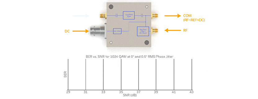
Figure 1 is the functional block diagram of Mini-Circuits’ Z4BT-2R15GW+ bias-tee/diplexer designed for modern SATCOM applications where the system’s reference oscillator frequency may have changed to 100 MHz. The reference (REF) port (3) can support from 10 to 100 MHz, and multiplex (inject) either of these frequencies onto the SATCOM RF waveform that is incident at the RF port (1).

That multiplexed waveform is output (along with DC bias) at the COM port (2). Of course, the converse is true as well wherein an incident RF/REF/DC combination at the COM port can be demultiplexed into its constituent parts, each at its respective port. If you have questions regarding our SATCOM multiplexer/bias-tee product line or capabilities, please contact sales@minicircuits.com.
A High-Performance 100 MHz Reference Oscillator vs. a Legacy 10 MHz Reference
SATCOM system designers continue to move to 100 MHz reference oscillators, generating it locally and distributing it to BUCs, LNBs, modems, encryptors, antennas, etc. Note that locally-generated 100 MHz references are not simply being derived as a harmonic of the legacy 10 MHz backbone. This is particularly important to note as we open our discussion on LO phase noise. After all, simply multiplying the 10 MHz reference by 10 to achieve 100 MHz increases the phase noise by 20log(N), where N is the multiplication factor. Consequently, 10 MHz multiplied to achieve 100 MHz would experience an additional 20log(10) = 20 dB of phase noise. That’s a huge increase in phase noise which would defeat the purpose of shifting the reference frequency to 100 MHz in the first place. Let’s baseline the oscillators themselves.
Table 1 shows our choices for 10 MHz and 100 MHz OCXOs. The offset frequencies appear across the top of the table and spot noise values (in dBc/Hz) appear for each OCXO. The 10 MHz reference is an NEL part (now Abracon) from their O-CS41-Series.1 Note that the spot noise at the lower frequency offsets (0.1 Hz, 1 Hz, and 10 Hz) has been disregarded and that the spot noise at the higher frequency offsets of 1 and 10 MHz has been determined by extrapolation. In effect we have taken long-term stability out of the equation and reduced the system performance degradation to one of integrated phase noise or rms phase jitter so that we can better quantify the impact on a system running 1024 QAM.

The 100 MHz OCXO chosen is the KVG O-22-ELPN-100M.2 Likewise, for this 100 MHz OCXO reference oscillator, we have disregarded spot noise at the 10 Hz offset and extrapolated to determine the spot noise value at 10 MHz offset frequency. This affords us a reasonable bandwidth over which to integrate phase noise (100 Hz to 10 MHz) as we work to determine the impact to overall system performance.
At smaller frequency offsets (only 100 Hz bears this out in Table 1), the 10 MHz OCXO is far superior in spot noise. A review of each data sheet shows that the 10 MHz OCXO exhibits -148 dBc/Hz at 10 Hz offset whereas the 100 MHz OCXO measures -110 dBc/Hz, a whopping 38 dB difference. While 10 MHz sources have long been prized for their excellent close-in phase noise, modern system design techniques that are beyond the scope of this article can overcome this shortcoming for 100 MHz reference oscillators.
At higher offset frequencies of 10 kHz to 10 MHz, the spot noise performance of the 100 MHz OCXO is approximately 20 dB better across the board. There are two distinct advantages to having the spot noise at higher offsets be so far superior for the 100 MHz OCXO:
- Integrating phase noise over a higher set of offset frequencies generally yields higher phase noise/phase jitter due to the higher integration bandwidth
- The 100 MHz OCXO requires 10x less multiplication to achieve the actual LO frequency than does the 10 MHz OCXO, a 20 dB advantage on top of 20 dB better spot noise at higher offset frequencies
Ku-Band SATCOM 1024 QAM Performance with 10 MHz and 100 MHz References
SATCOM receivers utilize local oscillators (LOs) to down-convert signals from high RF frequencies to either intermediate frequencies or to frequencies that are then suitable for direct conversion into the digital domain. The phase noise profile of the main reference (either 10 MHz or 100 MHz for our purposes) is of paramount importance, since it is used as a basis for the LO, which then transfers its noise directly to the down-converted signals. The impact on system performance can be quite severe, particularly for higher order modulation schemes such as 1024 QAM, since its large constellation density (32×32) makes it very sensitive to phase jitter.
A good way to demonstrate how the choice of reference frequency (10 MHz or 100 MHz) impacts SATCOM system performance is to first calculate the integrated phase noise/RMS phase jitter for each LO. Table 2 shows the RMS phase jitter and integrated phase noise for the 10 MHz and the 100 MHz OCXOs when upconverted to a 10750 MHz LO.

To calculate the increase in phase noise incurred in upconverting the 10 MHz OCXO to the Ku-band LO frequency of 10750 MHz, we have:
20log(10750/10) = 60.63 dB
To create a 10750 MHz Ku-band LO with a multiple of the 100 MHz OCXO, we calculate the increase in phase noise as
20log(10750/100) = 40.63 dB
Next, we add the requisite increase in phase noise to each of the spot noise values in Table 2, integrate from 100 Hz to 10 MHz and express the result in ⁰RMS of phase jitter (and also in dBc).
One thing that jumps out at us from Table 2 is that, from 1 kHz to 10 MHz, the spot noise values for the 100 MHz-derived Ku-band LO are some 20 to 40 dB better than their 10 MHz-derived counterpart. Naturally, therefore, when ⁰RMS of phase jitter for each LO is determined, the 100 MHz-derived LO has a significant advantage. Case in point, the 10 MHz-derived LO has a phase jitter of nearly 0.5⁰RMS and the 100 MHz-derived LO a phase jitter of just 0.007⁰RMS. In the following section, we boil these ⁰RMS phase jitter figures down into system performance parameters.
Phase Jitter Levels Mapped over the BER vs. SNR Graph
Less phase jitter in any SATCOM system with any modulation is certainly better. But perhaps nowhere is it more pronounced than with higher order QAM. Figure 2 shows the approximate performance curves for the two reference-derived LOs. The most striking characteristic of Figure 2 is that higher order QAM (in this case 1024) requires such significant SNRs to achieve acceptably low BERs, theoretically over 40 dB to achieve a BER of 10^-9 on the zero-phase jitter curve. We know that forward error correction (FEC) will vastly improve this, but we set that aside for the purpose of simplifying the example. The most pronounced system performance impact occurs when 0.5⁰RMS phase jitter from our 10 MHz-derived LO is received. Then the required SNR to achieve just a 10^-4 or 10^-5 BER is in the mid to upper 40s. In fact, if we were to extend the 0.5⁰RMS phase jitter curve to the right where the required SNR is 50 or 60 dB, we’d find that the curve flattens out and no further improvement in BER occurs with increasing SNR (the curve appears horizontally flat and asymptotic, in other words). The BER at which this occurs is referred to as the error floor. As shown, 0.5⁰RMS phase jitter is not usable for 1024 QAM when acceptable BER levels are required at reasonable SNRs.

The recommended maximum RMS phase jitter for 1024 QAM is a value of approximately one eighth of a degree RMS, or 0.125⁰RMS. Usually anything higher than this yields too high a BER or requires too high an SNR from the system. This 1024 QAM example, based on upconverting 10 and 100 MHz references to Ku-band 10750 MHz LOs shows the utility of the migration to 100 MHz references for SATCOM – lower integrated phase noise and lower RMS phase jitter leads to improved (lower) BER and less demand on the SATCOM system SNR.
Phasing Out
In this article we recognized the SATCOM industry’s need to increase data throughput by evolving to support wider BWs and higher order modulation schemes. Doing so requires lower phase noise to maintain acceptable BERs. The most significant area of improvement can be realized in the LO, which transfers its phase noise directly onto the up/down-converted RF carrier. Historically, 10 MHz references have been the basis for SATCOM LOs, but the industry has been migrating to 100 MHz. Mini-Circuits is in lockstep with that trend, fielding multiplexers that accommodate either a 10 MHz or 100 MHz reference input. Finally, we take the reader through a journey from a reference frequency of 10/100MHz, to a Ku-band SATCOM LO, to integrated phase noise/RMS phase jitter and its impact on BER and SNR for a 1024 QAM system. We concluded that the Ku-band LO using the 10 MHz reference had insufficient performance to support 1024 QAM, whereas the 100 MHz reference-derived LO exhibited excellent performance, approximating ideal 1024 QAM performance.
References
- O-CS41 Series
- O-22-ELPN-100MHz-ED3 (2).pdf
- QAM Bulks Up Once Again: Modulation to the Power of Ten
- Wenzel Associates, Inc., Spreadsheets/Programs, Allan Variance from Phase Noise (also calculates total RMS jitter over the specified bandwidth), March 23, 1998
Get in touch for orders or any queries: sales@rfdesign.co.za / +27 21 555 8400
Courtesy of Mini-Circuits