The Frequency Diplexer as a Combiner
Frequency diplexers (henceforth simply diplexers) serve to either divide (demultiplex) the frequency spectrum into two major sub-bands or perform the complementary function of frequency multiplexing where the two sub-bands are combined to form a full frequency spectrum. The focus of this article is the latter, the combining of two signals or sub-bands into one contiguous spectrum. Diplexers are a 3-port component comprised of 2 ports for the individual sub-bands and a third port defined as the full-band input or output, depending upon the orientation in which it is applied.
Diplexers are important because they allow two or more devices that operate on disparate frequencies to share a single transmission medium at the same time without interfering with one another. Since they reduce system cabling and complexity, they are considered economical to use for commercial wireless base stations, aerospace and defense systems, satellite communications (SATCOM) terminals, and for consumer electronics devices that operate over Wi-Fi and Bluetooth.
Diplexers come in many shapes and sizes and there are a multitude of technologies available with which to build them. Cavity, waveguide, dielectric resonator, substrate integrated waveguide (SIW), and microstrip/stripline diplexers are the most common types. Out of all these technologies, the one that arguably stands out as having the best balance of overall performance characteristics (SWAP-C) is the suspended substrate stripline (SSS) diplexer. Almost 50 years ago, Rooney and Underkoefler first proposed applying SSS technology to multiplexers1, but David Rhodes was most instrumental in developing and applying this technology throughout the decade that followed.2,3,4 Mini-Circuits’ SSS diplexers appear directly on the website and many more custom options are available. SSS technology is described in Mini-Circuits’ Understanding Suspended Substrate Stripline Filters, dated April 26, 2022.5
Combining Separate Frequencies – Diplexing vs. Power Combining
In traditional in-phase and quadrature power splitters and combiners, signals of different frequencies at separate ports experience a theoretical 3 dB loss plus the additional, practical insertion loss of the component itself. Diplexers split and recombine in a frequency-selective manner such that the sub-bands are subjected to only the practical loss of the component. Diplexers not only have a 3 dB advantage in loss over their power-combining counterparts, but many systems benefit from the inherent filtering that they provide.
Many diplexer configurations are possible by combining filters with low pass, high pass, and band pass filter characteristics. Perhaps the simplest diplexer is the low pass-high pass realization shown in Figure 1.

To fully define even the simplest of diplexers, several more characteristics are required. The nature of the stopband is important, since it may be reflective or absorptive. Additionally, the full-band output can be contiguous or non-contiguous, with a gap introduced between the low pass and high pass outputs. Finally, the high pass section is generally open-ended but may include a clean-up low pass filter.
Mini-Circuits’ Diplexer Use Case – 2.4/5/6 GHz ISM Band Applications
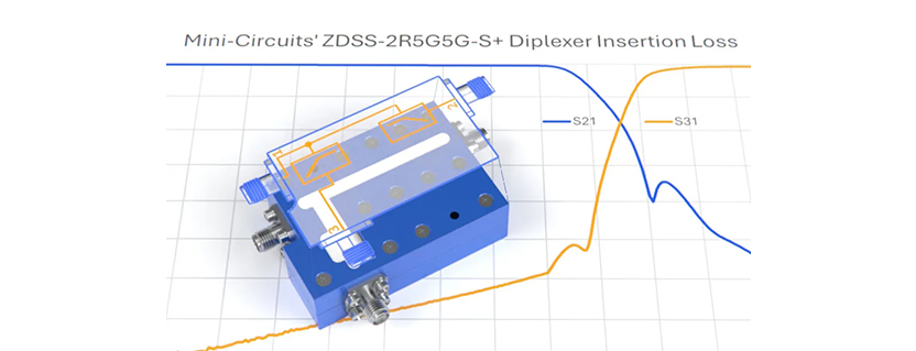
Mini-Circuits has designed and produced dozens of different diplexer models over the years, many of them using suspended substrate stripline (SSS) technology. One such diplexer is the ZDSS-2R5G5G-S+.

The diplexer supports low insertion loss and strong harmonic suppression. It can also support tri-band operation including the 6 GHz band, useful for modern Wi-Fi applications such as Wi-Fi 6E and Wi-Fi 7.

The Multi-Band Radar Application
Diplexers are also widely used in radar systems to combine S-band and C-band frequencies. A practical example uses the ZDSS-3G4G-S+, designed for high power handling and broadband performance.

This diplexer provides low insertion loss and strong isolation, preventing interference between bands and suppressing unwanted harmonics.
The Diplexer – A Natural Combiner
Diplexers provide an efficient way to combine signals of different frequencies with lower loss than traditional power combiners. They are widely used in wireless communication, Wi-Fi systems, and radar applications where multi-band operation is required.
References
- Rooney, J. P. and L. M. Underkoefler, Microwave Journal, 1978.
- Rhodes, J. D., Microwave Systems News, 1979.
- Mobbs, C. I. and Rhodes, J. D., IEEE Transactions, 1983.
- Rhodes, J. D., European Microwave Conference, 1986.
- Understanding Suspended Substrate Stripline Filters
Get in touch: sales@rfdesign.co.za | +27 21 555 8400
Courtesy of Mini-Circuits