Simulated Signals for Wi-Fi RF Channel Test
Often when testing RF systems and components, it is useful to consider the range of options available to perform different tests. One approach is to order the best test equipment for every application. This strategy will certainly support many different test applications with advanced features and precise measurements, but it is not the most cost effective and will often result in overkill, draining budgets for capabilities that may not even be used. When selecting test equipment, what is needed is a balanced approach. The type of test being performed, the parameters being measured, and the operator’s budget are all important considerations.
This paper will demonstrate the value of Mini-Circuits’ cost effective, RF peak & average power sensors for measurement of modulated signals, and the useful range of measurement settings that can be applied. It will also summarize the use of Mini-Circuits’ compact signal generator modules as a simple approximation to the time domain properties of a Wi-Fi signal.
1. Wi-Fi Radios
RF radios are used in many applications. Broadly speaking, an RF radio is composed of a power supply, a base band, a modulator, and an RF channel. This architecture can take the form of a cellular phone, a radar, a wireless router, a mobile radio or many other RF devices. The general building blocks are comparable in all cases.
In this example, we will examine a wireless router used to transmit a Wi-Fi signal in the 5 GHz band. First, we want to characterize the RF channel alone to understand its behavior. This requires an RF signal generator at the input of the RF channel to act as a stimulus and a RF power sensor at the RF channel output to measure the response. For our purposes, there is no need to carry real signalling information or actual data. When a real ‘live’ Wi-Fi test signal is not available, the typical time domain properties of a Wi-Fi waveform can be mimicked using the “dynamic pulse modulation” option of a Mini-Circuits RF signal generator.
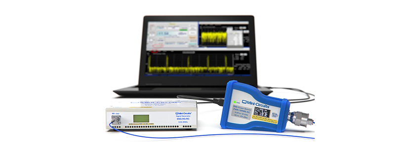
For this example, we will use Mini-Circuits’ SSG-9G-RC RF signal generator for the input stimulus and Mini-Circuits’ PWR-9PWHS-RC peak power sensor to measure the output response. This straight-forward approach will provide a measurement of average RF power, peak power, time domain profile, and identify other impairments without the need for a spectrum analyzer or other expensive equipment.
To begin, we will build the example time domain profile shown below using the Mini-Circuits signal generator, a repeating series of RF “bursts.” Each burst is a series of RF pulses on the order of 100 µs each and with varying power levels, separated by short intervals in the order of 10 µs; each burst is separated by a longer interval on the order of 10 ms.
In the following steps, we will set up the Mini-Circuits power sensor to measure the test signal:

2. Average Power Measurement
To get started with the measurement, connect the power sensor by USB or Ethernet and launch the GUI to view the average power of the signal on the main display. Follow the steps below to optimize the configuration of the sensor:
- Set the measurement frequency to match the Wi-Fi band being measured:

2. Click the Config button to set the key pulse power measurement settings:
- Sample period = 50 ms to capture multiple bursts
- Trigger mode = “Internal – On Rise” to start each measurement at the start of a burst of communication
- Trigger Level = -30 dBm (this needs to be set somewhere in the range of the rising edge of the pulse bursts)
- Video filter = “Peak (Filter Off)” to provide best resolution in the time domain
- Pulse Power Ref Level = -30 dBm (enabled) to calculate average power measurements based only on the pulse on times

3. Click “Apply” and “Exit” to return to the measurement screen where the average and peak power levels can be read:

The “Pulse Power Ref Level” setting is a powerful feature, optimizing the sensor for measurement of the communication bursts typical of Wi-Fi signals. With this feature disabled, average power measurements are calculated from the complete sample period of the power sensor. The effect is that the power level is averaged across the “on” periods when the radio is transmitting and the intervals between transmissions, leading to a lower level than expected. When a pulse power reference level is set, the sensor will discard any samples captured in the interval between communication bursts and calculate the true average power level of the radio during transmission.
3. Time Domain Profile Analysis
The power sensor software can also be used to provide a convenient view of the pulse / modulation profile in the time domain. Check the “Pulse Profile” option on the power sensor’s main display screen and then use Scale > Auto Scale from the graph menu to view the complete range of data:

4. Additional Measurement Settings / Options
4.1 Sample Period
Sample period can be used to trade the overall view of the profile against best resolution / accuracy of the data. Reducing the sample period to 800 µs in this example is sufficient to frame one complete burst within the graph trace. It also allows the sensor to calculate the average power with better accuracy since it can accumulate more data points within the relevant part of the signal.

4.2 Video Filter
Narrowing the video filter setting can help to reduce measurement noise of the profile plot. The trade-off is a slight reduction in the time domain resolution of the data and therefore a small reduction in measurement accuracy.

Video Filter = “Peak (1.5 MHz)”

Video Filter = “Peak (Filter Off)”
5. Summary
This paper summarises how Mini-Circuits’ peak and average power sensors can be used as a cost effective method for measurement of WiFi average power levels, and the useful measurement settings that can be applied.
By mimicking the RF time domain signal, we have also devised a way to characterize the RF channel providing a useful estimate of its performance while reducing the cost of test. There are times when a known, live signal is requiring for proper testing. By understanding the test requirements, measurements and budgets, there may be opportunities to reduce costs. This illustrates one such approach.
Explore Mini-Circuits Power Sensors >
Explore Mini-Circuits Signal Generators >
Get in touch for orders or any queries: sales@rfdesign.co.za / +27 21 555 8400
Courtesy of Mini-Circuits