Application Note: Delivering GNSS to Multiple Vehicle Systems
Connecting an automobile to the constellations that comprise GNSS requires an antenna and some very sensitive and specialized receivers. Each vehicular system has its own GNSS receiver, and those receivers supply GNSS coordinates to their respective systems, data which is utilized throughout the cabin. Keeping each receiver free from potential noise floor issues, spurious emissions or LO leakage from an adjacent receiver is paramount to the success of the system. Mini-Circuits offers a solution that not only isolates the receivers from one another, but is low-loss, tiny, rugged and reliable. Read on to find out how Mini-Circuits isolates RF front ends when connecting GNSS signals to multiple vehicular systems.
GNSS in Modern Day Vehicular Systems
GNSS (Global Navigation Satellite System) is really a catch-all acronym for the entire set of satellite constellations that provide global positioning, navigation and timing. As GNSS-derived positional accuracy has improved over the years from meters to centimeters (see Figure 1), the range of possible applications in automotive has greatly expanded and continues to do so.

Figure 1: GPS accuracy vs. year for the most recent several decades
When the vehicle is operational and in motion, GNSS data is concurrently utilized for navigation, vehicle tracking, a myriad of ADAS systems (e.g. lane position, adaptive cruise, collision avoidance), and V2X, telematics, eCall, and more. If the vehicle is involved in a crash, it is often turned off, yet must continue to utilize GNSS to provide data (coordinates) automatically to emergency services. Additionally, when turned off and theft is detected, the vehicle must engage its tracking protocols to assist with recovery. It is important that these emergency scenarios remain isolated from the many operational applications that already use GNSS data when the vehicle is turned on and in motion.
The objective is to determine how multiple vehicular systems can operate from a single GNSS antenna while remaining isolated from one another.
GNSS Use Cases – Feeding Multiple Systems Separately and Simultaneously
To operate systems that depend upon GNSS simultaneously, two or more GNSS RF inputs must be derived from a single feed/antenna so as not to increase the complexity and the size, weight, power and cost (SWaP-C) of the cabling in the process. In implementing the solution itself, SWaP-C is of paramount importance.
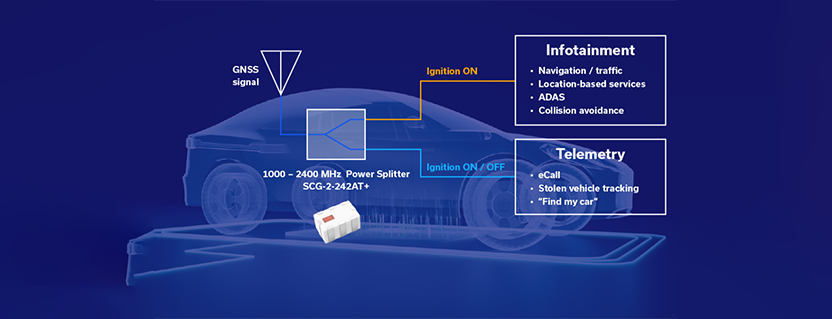
The most straightforward way of deriving a pair of nearly identical outputs from a single RF input is by using a power divider. Since the critical constellations (GPS, Galileo, etc.) fall approximately within the 1.1-1.6 GHz frequency band (L1 is 1.559-1.61 GHz, L2 is 1.215-1.254 GHz, and L5 is 1.164 to 1.214 GHz), the design shown in Figure 2 utilizes the AECQ-200-qualified SCG-2-242AT+ in-phase power divider with an external 0603 100Ω resistor. This RF power splitter operates from 1-2.4 GHz, a bandwidth that easily covers all the required L1/L2/L5 GNSS signals.

Figure 2: Block diagram of SCG-2-242AT+ power divider splitting the GNSS signal
Figure 2 illustrates how the SCG-2-242AT+ in-phase power divider furnishes isolated signals to those functions necessary with the ignition turned ON or those necessary when the ignition is ON or OFF. In the GNSS frequency range of 1.1-1.6 GHz, the typical loss is approximately 3.5 dB or less. The amplitude unbalance is typically less than 0.1 dB. The isolation between the two GNSS RF outputs ranges from 13 to 26 dB, and the return loss of each of the respective ports is excellent.


Figure 3: Plots of insertion loss, isolation, and return loss
The SCG-2-242AT+ splits the GNSS antenna input and achieves excellent electrical performance. GNSS signal levels are often very weak, so there is little room in the link budget for resistive splitting or other solutions when a traditional 3 dB in-phase power divider can be utilized. Having sufficient isolation prevents LO leakage and spurs from one receiver from contaminating another.
Tiny and Tough RF Power Divider – No Temperature Too Extreme
While RF performance is excellent, the mechanical properties are also impressive. The power divider is a Low Temperature Co-fired Ceramic (LTCC) component in a compact package. This efficient design can fit virtually anywhere on a crowded circuit board and has very low mass. Power handling is 2W and the component is competitively priced for high-volume automotive applications.
The SCG-2-242AT+ is monolithic, rugged and reliable, suited for harsh environments and wide temperature extremes (-40 to +105°C).
A Treasure Trove of Components – AEC-Q200-Ready and Available for Qualification
Mini-Circuits offers a wide portfolio of components for automotive applications. Nearly 80 components are already AEC-Q200 qualified, with many more available for qualification. Custom designs are also available, making Mini-Circuits a strong partner for automotive RF solutions.

Get in touch for orders or any queries:
sales@rfdesign.co.za / +27 21 555 8400
Courtesy of Mini-Circuits