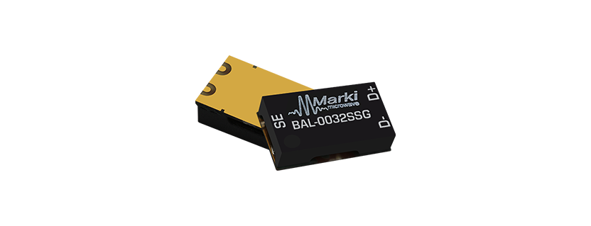
Marki Microwave BAL-0032SSG
The BAL-0032SSG is a surface-mount broadband balun, hand-tuned for optimal phase and amplitude balance over an industry leading 10 MHz to 32 GHz bandwidth. The BAL-0032SSG operates as an excellent choice for analog to digital converters, balanced receivers, baseband digital modulations, and signal integrity.
Features
- 2:1 Impedance Ratio
- 10MHz to 32GHz Balun (Balanced to Unbalanced Transformer)
- Transforms 50Ω to 100Ω Differential Output
- Tuned for Optimal Phase/Amplitude Balance
Applications
- Analog to Digital Converters
- Balanced Receivers
- Baseband Digital Modulation
- Signal Integrity
Port Functions
| Port | Function | Description | DC Equivalent Circuit |
|---|---|---|---|
| Port 1 | Common Port / SE (Unbalanced) | The common port is DC short to ground. |  |
| Port 2 | D+ / 0° Port (Balanced) | The 0° port is DC short to ground. |  |
| Port 3 | D- / 180° Port (Balanced) | The 180° port is DC short to ground. |  |
Specifications
Absolute Maximum Ratings
The Absolute Maximum Ratings indicate limits beyond which damage may occur to the device. Absolute Maximum Ratings are individual and should not be met in parallel. If these limits are exceeded, the device may be inoperable or have a reduced lifetime.
| Parameter | Maximum Rating | Unit |
|---|---|---|
| Maximum Operating Temperature | 100 | °C |
| Maximum Storage Temperature | 125 | °C |
| Minimum Operating Temperature | -55 | °C |
| Minimum Storage Temperature | -65 | °C |
| RF Power Handling 1 | 15 | W |
[1] Tested at 6GHz
Package Information
| Parameter | Details | Rating |
|---|---|---|
| Dimensions | – | 5.08 x 8.89 mm |
| Moisture Sensitivity Level | – | MSL 1 |
Electrical Specifications
The electrical specifications apply at TA=+25°C in a 50Ω system. Min and Max limits are guaranteed at TA=+25°C.
| Parameter | Test Conditions | Min Freq (GHz) | Max Freq (GHz) | Min | Typ | Max | Unit |
|---|---|---|---|---|---|---|---|
| Amplitude Balance | – | 0.1 | 20 | – | 0.5 | 1.3 | dB |
| Amplitude Balance | – | 20 | 32 | – | 0.5 | 1.5 | dB |
| Common Mode Rejection | – | 20 | 32 | – | 25 | 18 | dB |
| Common Mode Rejection | – | 0.1 | 20 | – | 25 | 22 | dB |
| Common Port Return Loss | – | 0.1 | 32 | – | 8 | – | dB |
| Impedance | – | – | – | – | 50 | – | Ω |
| Impedance Ratio | – | – | – | – | 2:1 | – | |
| Insertion Loss as Mode Converter | – | 0.01 | 32 | – | 5 | 8 | dB |
| Isolation | – | 0.01 | 32 | – | 8 | – | dB |
| Nominal Phase Shift | – | 0.1 | 32 | – | 180 | – | ° |
| Output Return Loss | – | 0.01 | 32 | – | 9 | – | dB |
| Phase Balance | – | 20 | 32 | – | 5 | 13 | ° |
| Phase Balance | – | 0.01 | 20 | – | 5 | 10 | ° |
Typical Performance Plots
Mixed mode scattering parameters are used to characterize differential circuits. For baluns, the 0° and 180° ports become a single 100Ω differential port and the common port remains a 50Ω common port.
Performance Graphs:
Insertion Loss
Return Loss
Isolation
Amplitude Balance
Phase Balance
Common Mode Rejection
Get in touch for orders or any queries: sales@rfdesign.co.za / +27 21 555 8400
Courtesy of Marki Microwave