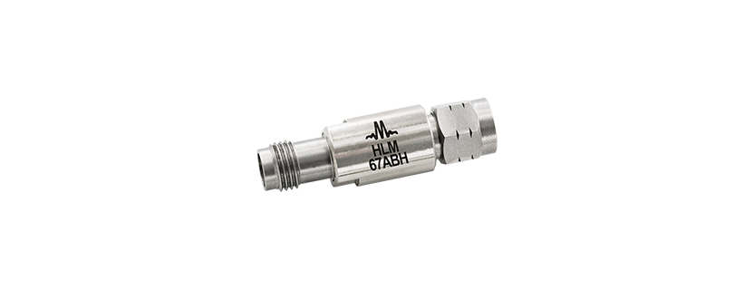
HLM-67ABH DC – 67 GHz High Frequency Limiter by Marki Microwave
The HLM-67ABH is a wide DC-67 GHz bandwidth GaAs Schottky diode signal limiter featuring high +27 dBm IP3 and high 1 W power handling. It offers low 1.35 dB typical insertion loss and excellent 19 dB typical return loss from DC through V band and has a typical 1 dB compression point of +8 dBm. Its high power handling makes it ideal for protecting sensitive components and for applications requiring high linearity.
Features
- Insertion Loss, 1.2 dB @ 35 GHz Typical
- Power Handling, 1 W CW @ 2 GHz
- Flat Leakage, +7 to +14 dBm Typical
- P1dB, +8 dBm Typical
Port Functions
| Port | Function | Connector Type | Description | DC Equivalent Circuit |
|---|---|---|---|---|
| GND | Ground | – | BH package ground provided through metal housing and outer coax conductor |  |
| IN | Input | 1.85F | IN is the RF input port and is diode connected for the BH package. |  |
| OUT | Output | 1.85M | OUT is the RF output port and is diode connected for the BH package. | |
Specifications
Absolute Maximum Ratings
| Parameter | Maximum Rating | Unit |
|---|---|---|
| Maximum Operating Temperature | 100 | °C |
| Maximum Storage Temperature | 125 | °C |
| Minimum Operating Temperature | -55 | °C |
| Minimum Storage Temperature | -65 | °C |
| RF Power Handling, Average | 1 | W |
RF Power Handling represents an instantaneous, catastrophic limit and it isn’t derated for frequency, temperature, pulse conditions, or unit to unit variation.
Package Information
| Parameter | Details | Rating |
|---|---|---|
| ESD | 250 to < 500 Volts | HBM Class 1A |
| Weight | Package name: BH | 10g |
| Dimensions | – | 32.8 x 9.5 mm |
Electrical Specifications
The electrical specifications apply at TA=+25°C in a 50Ω system. Typical data shown is for the connectorized BH-package limiter unless otherwise specified.
| Parameter | Test Conditions | Min Freq (GHz) | Max Freq (GHz) | Min | Typ | Max | Unit |
|---|---|---|---|---|---|---|---|
| Insertion Loss | – | 0 | 67 | – | 1.35 | – | dB |
| Return Loss | – | 0 | 67 | – | 19 | – | dB |
| Flat Leakage | – | 10 | 10 | – | 14 | – | dBm |
| Flat Leakage | – | 20 | 20 | – | 10.5 | – | dBm |
| Flat Leakage | – | 30 | 30 | – | 9.5 | – | dBm |
| Flat Leakage | – | 40 | 40 | – | 8 | – | dBm |
| Flat Leakage | – | 50 | 50 | – | 7 | – | dBm |
| Input IP3 | -5dBm Tone Powers at 1MHz Spacing | 0 | 30 | – | 27 | – | dBm |
| Input IP3 | -5dBm Tone Powers at 1MHz Spacing | 30 | 67 | – | 20 | – | dBm |
Typical Performance Plots
Insertion Loss Plot
Return Loss Plot
Output vs Input Power Plot
Input IP3 Plot
Input P1dB Plot
Mechanical Data
Outline Drawing

Get in touch for orders or any queries: sales@rfdesign.co.za / +27 21 555 8400
Courtesy of Marki Microwave