
Classical RF Filters: Selecting the Right Solution from Lumped Elements to High-Q Cavities
Modern RF and microwave systems operate in an increasingly congested spectrum, where filter performance often determines overall system capability. Whether protecting a low-noise amplifier from out-of-band interferers, suppressing transmitter harmonics, or isolating adjacent communication channels, filters are essential for maintaining signal integrity and maximizing system performance.
While all filters perform the same fundamental function—passing desired frequencies while rejecting unwanted ones—the technology used to implement the filter has a significant impact on key performance parameters such as insertion loss, selectivity, power handling, size, bandwidth, and cost. A compact lumped-element filter may be ideal for an IoT radio operating below 2 GHz, while a high-power radar transmitter may require a high-performance cavity filter capable of handling hundreds of watts with very low insertion loss. Between these extremes lie ceramic resonator, thin-film, and suspended substrate stripline (SSS) technologies, each optimized for a different combination of electrical and mechanical requirements.
Selecting the appropriate filter technology is therefore as important as selecting the desired electrical response. Choosing the wrong implementation can increase the receiver noise figure, reduce transmitter efficiency, enlarge system size, or unnecessarily increase system cost. Understanding the strengths and limitations of each technology allows engineers to optimize both system performance and overall product economics.
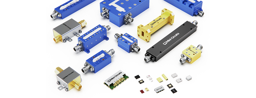
Mini-Circuits offers one of the industry’s broadest portfolios of classical RF filters, spanning approximately 1 MHz to 67 GHz using multiple implementation technologies. This diversity illustrates that no single architecture is universally superior; instead, each occupies a unique region of the RF design space.
Filter Responses: Choosing the Electrical Characteristics
Before selecting a physical implementation, designers must first determine the desired electrical response. The response defines how quickly the filter transitions from the passband to the stopband, as well as its amplitude and phase characteristics.
Four classical approximations dominate RF filter design:
Butterworth filters provide a maximally flat passband with no ripple, making them well suited for broadband instrumentation and measurement systems where amplitude accuracy is critical. Their gradual roll-off, however, requires higher filter orders to achieve strong adjacent-channel rejection.
Chebyshev filters introduce a controlled amount of passband ripple in exchange for steeper attenuation near the cutoff frequency. Because they offer an excellent compromise between complexity and selectivity, Chebyshev responses are among the most common choices in many RF systems.
Elliptic (Cauer) filters achieve the sharpest transition between passband and stopband by introducing transmission zeros. These responses are favored in crowded-spectrum applications—including radar, electronic warfare, and satellite communications—where high rejection close to the passband is essential.
Bessel filters prioritize linear phase and nearly constant group delay rather than maximum selectivity. Although their attenuation skirts are relatively gentle, they preserve waveform fidelity and are often selected for pulse transmission and time-domain measurement systems.

Figure 1. Characteristics of various filter types.
Regardless of the physical technology, these response characteristics form the foundation of most RF filter designs.
Choosing the Right Filter Technology
Lumped-Element Filters

Lumped-element filters are the workhorse of the RF industry. Constructed from discrete inductors and capacitors, they offer the smallest size and lowest manufacturing cost while supporting lowpass, highpass, bandpass, and bandstop configurations.
Their greatest strengths are compact size, rapid development, and economical high-volume production. They are well suited for commercial wireless products, industrial electronics, IoT devices, and general-purpose instrumentation operating below several gigahertz.
The primary limitation is resonator quality factor (Q). As frequency increases, parasitic inductance, capacitance, and conductor losses become more significant, increasing insertion loss and reducing selectivity. For most applications, lumped-element filters are best suited to lower microwave frequencies where their performance, size, and cost provide an outstanding overall value.
Ceramic Resonator Filters

Ceramic resonator filters provide substantially higher unloaded Q than lumped-element networks by storing electromagnetic energy within high-dielectric ceramic resonators. The higher Q translates directly into lower insertion loss, narrower bandwidths, and steeper rejection characteristics.
These filters occupy the middle ground between compact PCB-based filters and larger cavity filters, making them an excellent choice for cellular infrastructure, satellite communications, microwave backhaul, and aerospace systems. Modern cross-coupled and non-resonating node (NRN) topologies further improve selectivity by introducing transmission zeros without significantly increasing size.
Ceramic filters are typically chosen when low insertion loss and high selectivity are required but the size and cost of cavity filters cannot be justified.
Thin Film Filters

Thin film filters use photolithographically defined transmission-line structures fabricated on low-loss dielectric substrates. Because conductor geometry is established using semiconductor-style manufacturing processes, these filters offer excellent dimensional accuracy and unit-to-unit repeatability.
Thin film technology is particularly attractive at microwave and millimeter-wave frequencies where small dimensional variations can significantly affect electrical performance. Applications include satellite communications, phased-array radar, test instrumentation, and high-frequency commercial wireless systems.
Compared with cavity filters, thin-film designs are smaller and easier to integrate into compact assemblies while still providing excellent frequency accuracy and low insertion loss.
Suspended Substrate Stripline Filters

Suspended substrate stripline (SSS) technology combines the benefits of planar transmission lines with the low dielectric loss of an air-filled structure. By suspending a thin dielectric substrate inside a precision-machined enclosure, much of the electromagnetic field propagates through air rather than dielectric material, significantly reducing insertion loss.
SSS filters are widely used in broadband radar, electronic warfare, satellite communications, and laboratory instrumentation where wide bandwidth, high power handling, and excellent return loss are critical. Although larger and more complex than conventional PCB-based filters, they provide an excellent balance of bandwidth, efficiency, and environmental robustness.
Cavity Filters

Cavity filters represent the highest-performance implementation of classical RF filter technology. Precision-machined metallic resonators exhibit exceptionally high unloaded Q, enabling extremely low insertion loss, outstanding power handling, and very sharp rejection characteristics.
These advantages make cavity filters the preferred choice for high-performance receivers, satellite payloads, cellular base stations, microwave backhaul links, and defense systems where every decibel of loss and every dB of stopband rejection matter.
The tradeoff is size, weight, and manufacturing cost. These filters are large, heavy, and expensive compared to other technologies. Nevertheless, when ultimate electrical performance is required, cavity filters remain the benchmark against which other technologies are measured.
| Technology | Primary Strength | Typical Tradeoff | Best Applications |
| Lumped Element | Smallest size, lowest cost | Limited Q at higher frequencies | IoT, wireless devices, instrumentation |
| Ceramic Resonator | High Q, excellent selectivity | Moderate size and cost | Cellular, satellite, aerospace |
| Thin Film | Precision and repeatability | Moderate power handling | Microwave, mmWave, test systems, Aerospace and Defense |
| Suspended Substrate Stripline | Wide bandwidth, low loss | Larger mechanical structure | EW, radar, broadband communications |
| Cavity | Ultimate performance | Largest size and highest cost | Radar, satellite, infrastructure, Aerospace and Defense |
Table 1. Comparing Filter Technologies.
Selecting the Best Filter Technology
The ideal filter implementation depends on balancing several key requirements:
- Frequency range: Higher frequencies increasingly favor distributed technologies such as thin film, SSS, and cavity filters.
- Bandwidth: Broadband applications often benefit from SSS designs, while narrowband systems typically favor ceramic or cavity filters.
- Insertion loss: Low-loss receiver front ends generally require high-Q resonator technologies.
- Power handling: High-power transmitters are best served by SSS or cavity implementations.
- Size and weight: Portable equipment generally favors lumped-element or thin-film solutions.
- Cost: Lumped-element filters provide the most economical solution for high-volume commercial products.


Figure 2. Capability matrix for classical filter technologies.
No single technology is universally superior. Instead, each occupies a unique position within the RF design space, optimized for different combinations of electrical performance, manufacturability, and system constraints.
Conclusion
Advances in materials, electromagnetic simulation, and manufacturing have significantly expanded the capabilities of classical RF filter technologies. From miniature lumped-element filters supporting compact wireless devices to high-Q cavity filters enabling mission-critical radar and satellite systems, today’s engineers have a wide range of options for optimizing RF performance.
By understanding the strengths and limitations of each technology, designers can make informed tradeoffs among insertion loss, selectivity, bandwidth, power handling, size, and cost. The result is not only a better filter, but a better overall RF system—one that achieves the required performance with the most appropriate and economical implementation.
Get in touch for orders or any queries: sales@rfdesign.co.za / +27 21 555 8400
Courtesy of Mini-Circuits
